The marketplace for additive manufacturing hardware
Evaluate, select, and source AM systems from trusted suppliers.

Our partner manufacturers


Testimonials
Professional AM buyers use Aniwaa

«
Aniwaa was a decisive tool in our 3D printers evaluation process, they helped us obtain the information and quotes we needed quickly. »

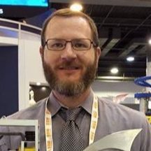
Senior Lecturer @Imperial College London
«
Aniwaa and their partners were of great help in the decision-making process to select a carbon fiber 3D printer matching our requirements. »
Engineer @Leonidas Engineering Solutions

«
Aniwaa helped our lab identify a state-of-the-art but affordable solution to 3D print complex cardiac anatomies.
The process was very smooth and time-efficient. »
The process was very smooth and time-efficient. »

3D simulation manager @IRCCS San Donato
How it works
- EVALUATEResearch and benchmark AM systems using our tools and resources.
- SELECTIdentify products that match your needs and technical requirements.
- PURCHASEGet connected with trusted suppliers to order samples, get quotes, and finalize your order.