An overview of 3D scanning for part inspection


Part inspection and quality control
Part inspection is an essential task to quality control, a process used to establish conformity between produced parts and their original, intended specifications. This is achieved by constantly checking parts at different steps along the production line, from the raw material’s composition to the final testings of finished products, thus ensuring the part properly carries out its intended functions.
Part inspection usually relates to metrology. It involves measuring and reporting dimensional attributes of components while evaluating whether they meet the fabrication tolerances or not.

Besides ensuring dimensional conformity to the intended specifications, part inspection also functions as a gauge to manufacturing processes; consistent dimensional deviations or defects in produced parts may indicate an issue with the production line, which must be quickly addressed to avoid wasting time and materials with off-spec parts.
The inspection itself can be done by a wide array of methods and instruments. Even the simplest measurement devices like rulers, calipers, and gauges could offer enough precision for some applications, but manual tasks are inefficient and lack repeatability due to operator variability.

Until recently, Coordinate Measurement Machines (CMMs) were the standard solution for accuracy and reliability in part inspection. Yet, operating these machines can be quite labor-intensive, involving tedious tasks like setup, programming, and the actual measuring procedure. In addition, CMMs usually demand temperature-controlled rooms and expensive maintenance and calibration.
Optical metrology
Optical devices can be very effective alternatives when it comes to quality control. These instruments rely on light instead of contact probing to measure parts’ geometrical and dimensional properties.
They work by projecting light onto an object and then retrieving the reflections with highly sensitive sensors– a technology called light or laser triangulation. These devices can effectively “see” the object by comparing the emitted and received, reflected light (similar to bat echolocation but using light instead of sound). Structured light technology can also be used for part inspection; light patterns are projected onto the part, and the patterns’ deformations are measured by the scanner’s software to determine the part’s shape.

Optical measurements are nondestructive and make no physical contact with parts, being particularly useful for measuring deformable or soft surfaces without risking damage to them. Optical measurement equipment is often faster and more accurate than contact-based instruments and can also measure regions that touch probes can’t reach due to physical obstacles, like pockets or holes.
3D scanning for part inspection
3D inspection or 3D measurement is any measurement method that captures and displays data in a three-dimensional format.
3D scanning is the most popular 3D measurement technique for part inspection. It has become an essential tool for quality control procedures in many industries due to its versatility, accuracy, and digital integration.
You may also like:
The best metrology 3D scanners

It can gather large amounts of data in very short intervals – some 3D scanners can gather over 1,000,000 individual points per second – with impressive precision and resolution. This allows optical scanning devices to generate highly detailed and accurate 3D models regardless of the part’s geometric complexity (although the more complex the objects are, the more challenging they are to capture).
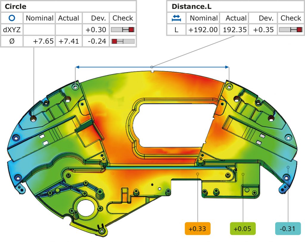
The obtained 3D models are digitally compared to the original “theoretical” CAD file and checked for geometric and dimensional variations. Specialized inspection software like GOM Inspect or Geomagic Control X generate automated reports and visual analysis aids like deviation color maps that offer valuable insights.
Besides checking for dimensional conformity, engineers can use the data from 3D scanning to optimize manufacturing processes, mitigating deviations and defects altogether. Digital inventories and archives can also be created; once scanned, parts that have already shipped can be re-evaluated at any time through their virtual copy, more commonly known as “digital twin”.
3D scanners are convenient devices, and their ease of use is yet another great advantage. The versatility they provide is also a plus, ranging from stationary systems to handheld portable devices, allowing measurements to be taken directly on the shop floor.
Automating inspection
Part inspection remains a challenge in industries such as aerospace or medical where quality and precision are of utmost importance. In many cases, spot-checking inspection is not enough, and every part is required to be thoroughly validated and, often, certified.
Automated systems are the ultimate solution for efficient and continuous part inspection. Such systems can come in the form of scanning booths, or as 3D scanners mounted onto robotic arms. In an ideal scenario, automated scanning stations would be integrated directly at every step of the production line, levelling up any factory’s manufacturing quality.
You may also like:
Practical guide to automated metrology 3D scanning with GOM solutions
Continuous monitoring is the key to automation. The whole concept of Industry 4.0 relies on vast amounts of real-time data, and 3D scanning can effectively become the eyes of digital factories.