English
  Français
Reviewing the Compact, Versatile, and Powerful SIMSCAN from Scantech


Introduction
It’s our first time reviewing a scanner from Hangzhou-based Scantech, so let’s take a quick look at the company and its background. Before 2015, the 3D laser scanner market in China was completely dependent on imports. On top of that, overseas brands had many restrictions in sensitive industries such as military and aerospace. These factors contributed to Scantech’s creation, which launched its first laser 3D scanner in 2016 (the PRINCE) to topple this monopoly.
Today, Scantech markets numerous 3D scanners, from handheld solutions to automated metrology stations. The company recently established a subsidiary in Stuttgart to be closer to their EMEA clients with a multilingual team (English, French, German, Arab, and Spanish-speaking). The goal is also, notably, to work towards obtaining important certifications like the VDI/VDE 2634 or ISO 17025. Such certifications are one of the most important entry barriers for 3D scanner manufacturers, along with software (functionalities, speed, UX, …).
Note that, according to Scantech, the company already follows relevant VDI/VDE and ISO standards throughout its manufacturing processes.
Overview of the SIMSCAN’s specs
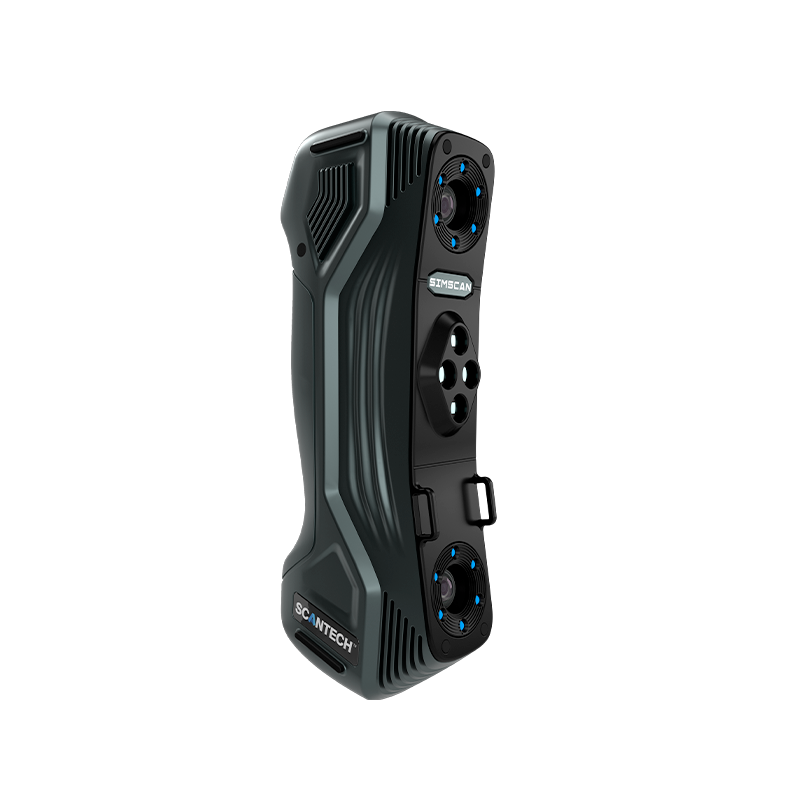
The SIMSCAN is extremely lightweight for a handheld 3D scanner, weighing only 570 grams. It’s also very compact– the absolute smallest in its class– with dimensions of 203 x 80 x 44 millimeters. These specifications make the SIMSCAN easy to use in hard-to-reach places and ergonomic for long scanning sessions. The Scantech design team even earned a Red Dot Design Award in 2021 for the SIMSCAN.
| Category | Handheld |
| Technology | Laser triangulation |
| Accuracy | 0.02 mm |
| Weight | 0.57 kg |
| Price | $ 30,000 |
Single-handed Control
SIMSCAN’s full-metal housing provides solid protection and ensures extraordinary durability. Weighted only 570 g and sized 203 × 80 × 44 mm, SIMSCAN portable 3D scanner brings unparalleled simpleness for scanning anything with one hand.
Because of its hollow structure, it dissipates heat more effectively. The 3D laser scanner is efficient at performing measurements with low power consumption. Thanks to its versatility, it can meet a wide range of needs of 3D measurements.
Narrow-space Measuring Booster
Compared with its competitors, SIMSCAN has a much shorter camera distance of 130 mm, which forms a steeper view angle to 3D scan narrow spaces. Therefore, SIMSCAN is more capable of capturing accurate and complete data in hard-to-reach areas like deep grooves and ensures users to capture full-field data.
Detail, Everywhere
With its built-in HD cameras and three scanning modes, it realizes high-precision scanning with an accuracy up to 0.020 mm. It can accurately capture the 3D data of objects with complex surfaces or in confined areas.
Technology-wise, the Scantech SIMSCAN uses blue laser triangulation, offering three different laser modes: ultrafast, hyperfine, and deep hole scanning. It can achieve a resolution down to 0.025mm with an accuracy of 0.020mm, capturing up to 2,020,000 points per second.

The value proposition is strong and clear: metrology-grade precision in a first-of-its-kind, lightweight 3D scanner for under half the price of current comparable, competing solutions.
Before we dig into our Scantech SIMSCAN review, here is our summary of its pros and cons:
 Pros
Pros
- Very sleek and ergonomic design
- Compact dimensions and light weight
- Three scanning modes and ability to post-tune the resolution
Cons
- Software could be more intuitive
First impressions
The scanner’s ultra-small size and feather weight are remarkable, as are its sleek design and ergonomics. It is a pleasure to pick up and use!

Zooming in on the details, the sensor features a robust metal casing with well-integrated optics. It is dressed up in a plastic, mesh-like shell for added protection from everyday use (and the user’s hand sweat and heat!). The shell enables you to get a good grip on the scanner. There’s also a useful elastic strap attached to the body of the scanner; you can wave the scanner around without fear of dropping it.

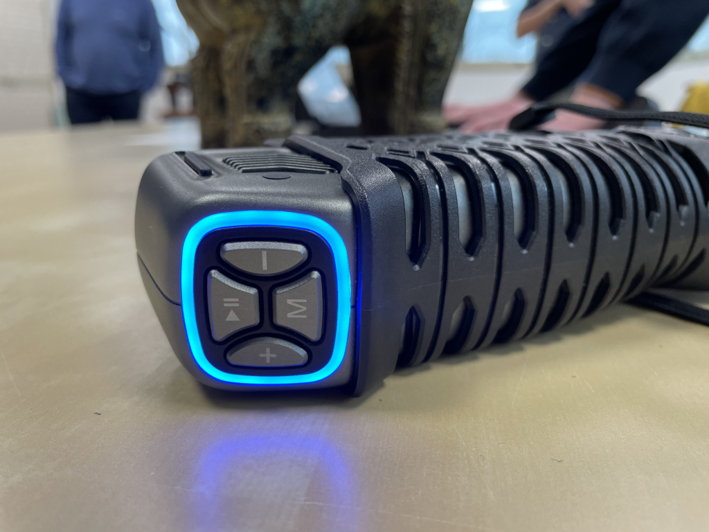
Four buttons atop the sensor are directly accessible by thumb or index finger (depending on the size of your hand and your preferred holding position):
- The top one with the stop/play icon serves to start, pause, or stop a 3D scan.
- The left and right ones allow you to zoom in and out of the software’s display and are used to get the most of the computer screen size at any given time.
- The bottom one lets you toggle between the 3 different scanning modes.
On the SIMSCAN’s bottom side are two ports to connect the scanner to the PC and power outlet. The cables fit nice and tight:

The SIMSCAN comes in a practical and compact transportation case. It holds the 3D scanner, its cables, and the calibration plate firmly in place with dense foam.
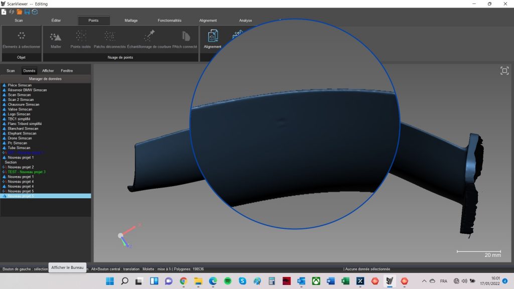
In terms of software, the SIMSCAN works with Scantech’s ScanViewer. Its interface is pretty straightforward and well-organized.
Our experience with the SIMSCAN
Calibration
The calibration plate measures about 30 x 20 cm. It is cleverly glued to the underside of the foam from the transportation case. Simply remove the foam and put it upside down, and you’re ready to calibrate (once your SIMSCAN and PC are up and running, of course).

The calibration process is quick and efficient if you have some previous experience with 3D scanners. As usual, it consists of aiming at the calibration plate with the SIMSCAN in hand. You explore different configurations one by one, i.e., a mix of being close and far away from the plate while tilting the scanner at different angles.
The software displays two shapes– an ellipse and a parallelogram– that help properly position and orient the 3D scanner during the process. However, we noted that the interface was neither clear nor intuitive. A more refined tutorial could be useful for new users.
Watch the short video below to see how the SIMSCAN’s calibration works:
Starting a scan
Before getting started with a 3D scan, we always take a minute to evaluate the properties of the part we want to digitalize:
- Size: Is it large, medium, or small?
- Geometry: Is it a long or thick part? Is the bounding box of the part balanced?
- Level of detail: Is the part made of large flat areas? Does it have intricate details or pockets? Do some areas feature embossing or engraving?
- Texture: Is the part smooth or rough? Is there a single texture or multiple ones?
- Color(s) and transparency: Does the part have transparent or translucent areas? Is the part shiny and metallic? Is the part bright white or black? Is the part matte black?
Answering those questions helps determine the best course of action to 3D scan the part, and therefore where to position markers. You can also determine if the use of mattifying spray like AESUB is needed to speed up the process or enhance the results.
Marker placement is quite an important deal when it comes to precision 3D scans. Remember that, at all times, the sensor must “see” at least 3 markers to perform a proper triangulation. It is therefore important to check, once you have positioned all the markers, that all areas of the part are properly covered. This verification will later ensure a smoother 3D scanning process.

Now, to the actual scanning!
The first scan (of a series of scans for 1 object) is a reconnaissance scan; the software generates a precise “skeleton” of the part based on all the markers. This scan is used as a backbone for the software to properly align and position every frame during the 3D scanning process. The principle is kind of like a connect-the-dots puzzle for kids, where you first connect the dots before being able to color the drawing. This action is done in minutes.
Once you have your skeleton, you can then choose the different parameters for your scan.

Resolution
Each project stores several 3D scans, aligned together. The resolution of the 3D scans between different projects must be consistent so they can be aligned together.
Note: A project is a group of scans. There can be multiple projects for a single object. For example, you can create a project for the top side of your object, and when it’s time to flip it over, you are actually starting a second project.
You won’t be bothered by a resolution that’s too low, because it is always possible to toggle the 3D scanner to its hyperfine scanning mode. Note that the latter mode does not have a fixed resolution, but depends on the initial resolution of the project. It can go up to 8 times the initial resolution, at the cost of dramatically increasing the 3D scan file size. This hyperfine 3D scanning mode is a major innovation brought by Scantech; we will deep dive into its functioning later on in this article.
For most of the 3D scans performed during our hands-on SIMSCAN review, we set the resolution to 0.5 mm to be able to conduct a lot of testing in a limited amount of time. But worry not, we also tested the hyperfine 3D scanning mode for an all-around performance review of the SIMSCAN.
Watch the SIMSCAN in action:
Exposition (automatic or chosen)
Depending on the part’s color, it is possible to change the 3D scanner’s exposition. A high exposition will boost the illumination power of the projector by leveraging the sensitivity of the cameras. It is very similar to changing the ISO of a camera when taking photographs in dark environments.
But, as is the case with its 2D counterpart, cranking up the exposition has drawbacks. It makes dark areas easier to 3D scan, but shiny areas will blind the sensor and tamper with the ability to 3D scan.
We recommend using the automatic exposition mode first to capture most of the part, before manually adjusting the parameters to more effectively 3D scan the out-of-range areas (ones that are too dark or bright).
Scanning modes
The SIMSCAN features three different scanning modes:
- Ultra-fast: 11 blue laser crosses. Allows you to quickly capture large surfaces and generate a first 3D scan in minutes. In most situations, this mode will suffice. Speed-wise, it even allows the SIMSCAN to be competitive against structured light 3D scanners on large areas, such as a car door.
- Hyperfine: 7 blue parallel laser lines. Once the part has been roughly drafted with the ultra-fast scanning mode, it is recommended to slowly scan the part’s surface with this mode to capture a higher level of detail.
- Deep hole scanning: 1 extra blue laser line. This last mode is dedicated to the 3D scanning of very small details. Since it only uses one laser line, this mode is excellent for 3D scanning holes or difficult-to-access geometries. Note that the scanner’s small size alone is also an advantage for this type of difficult scanning (more about that here).
Hyperfine mode
This mode relies on 7 blue laser lines. What is really interesting about this mode is that it can be triggered at any time from within an existing project. It will always work within the previously set resolution of the project, but will be able to upgrade it by a factor of 8. We used it after the complete 3D scan of a demo part that had very small details in two specific places, a very common use case.

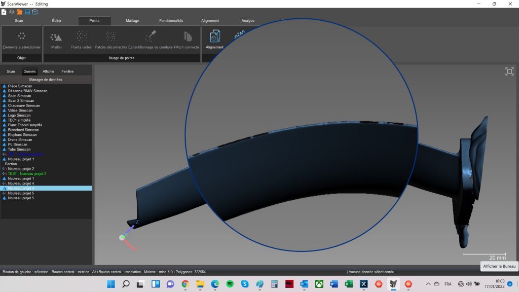
First, in the software, we indicated the precise locations of where the ultra-detailing was to be performed. This can easily be done by selecting it directly from the existing 3D mesh of the part, with various selection methods. We used the simple lasso selection tool to identify where we wanted to obtain more detailed information.

Depending on which selection tool you choose, the software can also include the opposite face of your selection. Hence, if you don’t pay close attention, you can later be prompted to scan the other side of the part. For example, on the demo part we scanned (see below), we just wanted to grab more details about the embedded coin and the label on the top of the part, and not the flat underside.
Second, we switched to the hyperfine mode and started adding information to both specific zones. In a few seconds, the task was completed and the results were amazing.

If you push the SIMSCAN’s parameters to the max, you can get even cleaner results, like in the screenshot below (from Scantech):

Note that the file size of the 3D scan dramatically increases once you have detailed information. In our case, it was a 40% increase for a small zone. That’s why the hyperfine mode is a really interesting feature. It allows you to quickly capture a part in a few minutes, obtain a small file, and later refine only a specific area while increasing the file size in the most efficient way.
In a way, it reminds us of the now-common “optimized triangulation” feature in other software suites, which also reduces file size by decimating information on simple geometries, like a flat surface.
Reliability
It is worth mentioning that after several hours of non-stop operation, we did not notice any drop in the SIMSCAN’s performance. The sensor is capable of regulating its own temperature to avoid overheating and, thus, capturing flawed or “warped” data. This also helps prevent a phenomenon called “drift”, when a 3D scanner’s accuracy drifts further and further away from its original accuracy during long 3D scanning sessions.
3D scan results
We carried out scans on several objects to try out the SIMSCAN in different conditions.
Khmer lion statue
This is a beautiful statue that Elliot bought at a Khmer market in Siem Reap before moving back to France. Its stone surface is polished and therefore slightly reflective, and boasts hundreds of tiny details– the perfect challenge.
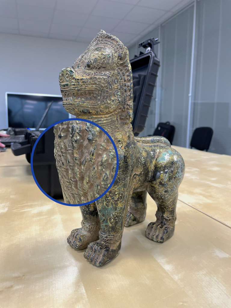
The SIMSCAN did extremely well here. The original file’s size is however huge, at 141.3 MB. The 3D viewer below shows an optimized version (the original file includes a higher level of detail):
Transistor radio
The radio, a hand-me-down from Ludivine’s side, was another good challenge for the SIMSCAN with a nice mix of details and textures. It sports a black leather surface, chromed details, a transparent surface (a sort of window covering the radio stations), repeated geometry (the white “grille”), and other small features like the radio selection wheels.
We used AESUB spray on the transparent, window part and were able to capture the whole radio in minutes. The initial result is quite good. With more time on our hands, we could have perfected the mesh with additional sweeps and post-editing.
Turbine blade
We scanned a small turbine blade that our partners had in their office. It’s made of metal with very thin edges, which can be challenging to scan.

The SIMSCAN did a great job on the entire part except on some of the edges. With additional scanning time, we could have successfully captured the edges, but we found that it was quicker to just spray it. Here are before and after screenshots from ScanViewer:
Note: We use spray as an easy way to further speed up the scanning process and to better capture challenging parts.
Conclusion: Our verdict
Scantech has impressed us with an excellent product that feels, looks, and works great. The SIMSCAN’s price-to-performance is outstanding and contrasts greatly with comparable 3D scanning hardware. We found that it worked very, very well on small and complex details, especially with the hyperfine mode. It is also able to capture dark and shiny surfaces relatively easily, though mattifying spray (we used AESUB Blue) can be necessary in some cases to obtain even better or quicker results.
Software-wise, ScanViewer could use some UX improvements. The instructions aren’t always clear, especially during the calibration process. While there is a learning curve, the software is globally intuitive to use and offers interesting features. Its hyperfine, ultra-detailing mode is one of its greatest strengths. ScanViewer also offers basic metrology capabilities with automated report generation.
TL;DR: The SIMSCAN is an excellent product, and with Scantech working towards obtaining VDI/VDE and ISO certification, it’s going to become harder and harder to compete with it. Their Stuttgart center also enables Scantech to be closer to their EMEA customers– and in their native languages. Aside from certification, software development is the only main step left (and a big one it is) for Scantech to climb before joining the same league as established brands like Artec or Creaform. With that in mind, it is always possible to mix and match hardware and software from different brands.
Many thanks to Fabrice and Florian Goussu from Boréal 3D for their warm welcome.