English
  Français
Reviewing the Anisoprint Composer A4, a unique continuous fiber 3D printing solution


A few words about Anisoprint
Amazed by the composite material possibilities unlocked by 3D printing technology, four Russian friends and two professors with some serious mechanics, engineering, and material science backgrounds founded Anisoprint together in 2015. Three years later, they moved their headquarters to Luxembourg, where Anisoprint products are assembled and shipped out to customers worldwide.
The team has earned several awards since then and grown into a 40-person company. Around 30 of them work on R&D for machines, materials, and software; continuous development is literally part of their DNA. Anisoprint also recently opened up a branch in Japan to better serve the Asian market.
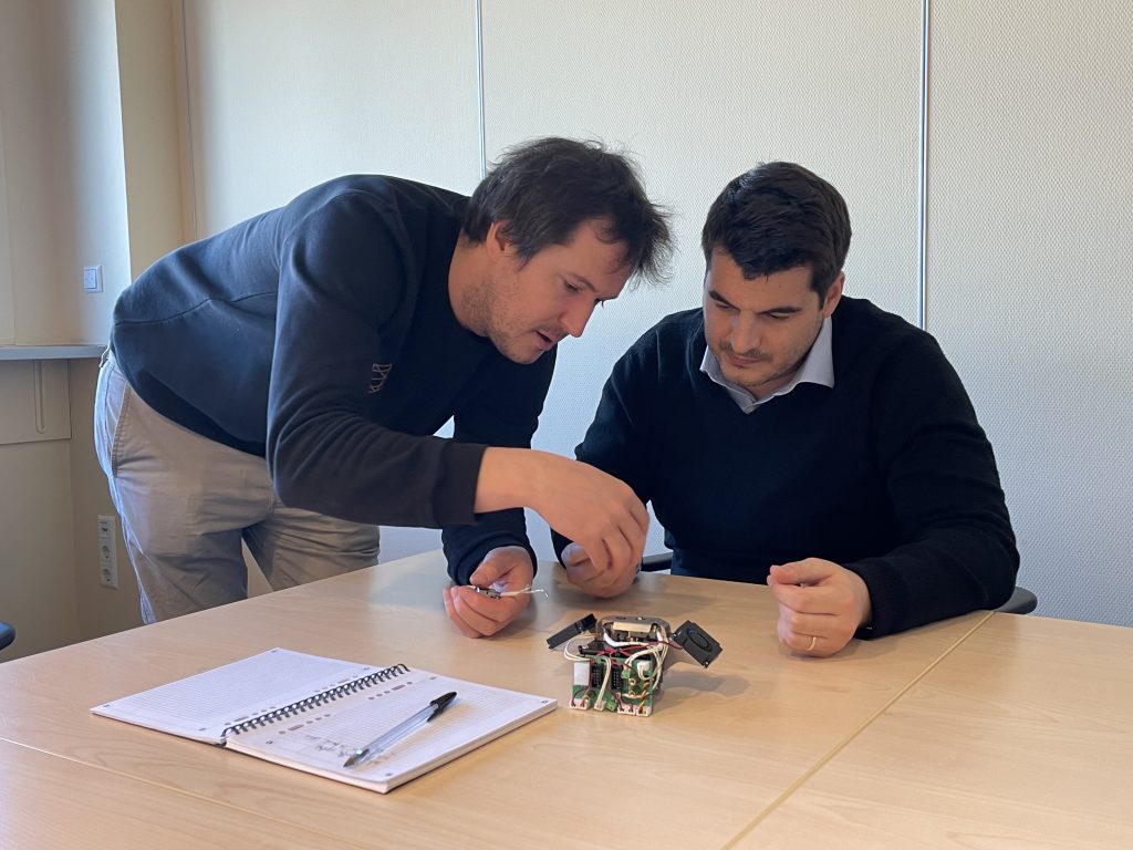
We were delighted to visit the Lux team, led by Anisoprint’s smart and inspiring CEO Fedor Antonov. Fedor and his colleagues bestowed us with some excellent insights on composites and how we can leverage them with 3D printing to rethink the way we engineer. They gave us a tour of their factory floor and assembly line, too. Everyone was passionate about their subject and we could really feel their energy.


In this review article, we try our best to convey this enthusiasm and our learnings about 3D printing composites, while focusing on the Composer A4 3D printer, its software, and the user workflow. Before we move on to give a quick overview of composites and unfold the actual review, here is a quick summary of the Composer A4’s pros and cons.
 Pros
Pros
- Excellent price-to-performance ratio
- Technology with unique possibilities
- Intuitive, feature-packed Aura software
- Open material options
- Insightful Anisoprint Academy
Cons
- Outdated user experience
- Small screen
- Gcode for calibration
- Manual bed leveling
- No filament sensor
An overview of carbon fiber and CFC tech
Anisoprint’s patented technology is called Continuous Fiber Co-extrusion (CFC). To fully understand its value, we must first take a step back and look at composites in general.
Composites 101
A composite is, in its largest meaning, “something that is made of different parts.” In engineering, the definition of composite is narrowed to “a material made up of more than one substance that is used for building things.”
The ultimate goal is to leverage the strengths of two or more different materials while balancing their weaknesses (or even canceling them out), and even to unlock new, unique properties in the synergy of the constituent materials.
Another simple definition of composite is “a mixture of two materials, one of which makes the other stronger.” This is precisely what happens when carbon fiber, as the reinforcing material, is added to plastic, the matrix material. In this case, the matrix serves as a way to bind the fiber and shape it as desired. We can take reinforced concrete– a composite– as an easy example: steel rods reinforce a concrete matrix.
Materials composed of fibers are naturally present all around us, like wood (cellulose fibers and lignin), but also inside us– our bones are composites, made from hydroxyapatite and collagen fibers. The fibers make these materials highly anisotropic, meaning that they are very strong in one direction.

For example, you can easily vertically chop a log in half with an axe, but you’d need a saw to cut it horizontally (or spend a lot of time hacking at it with your axe).
Fiber composites are thus popular for a range of applications and industries where strength and resistance are required.
Carbon fiber and 3D printing
In 3D printing, there are several ways to reinforce plastics with carbon fiber (CF), or any other available fiber (e.g. glass fiber) for that matter. We will focus on the two main methods: chopped carbon fiber and continuous carbon fiber.
Chopped carbon fiber
With this technique, the carbon fiber reinforcement is added to the matrix material, often a thermoplastic, before the 3D printing process. It is basically a regular plastic filament that has been mixed with microscopic cuts of carbon fiber (hence the term “chopped” carbon fiber). Taking the reinforced concrete example, it would be like pouring hundreds of small steel rods into a concrete mixer.
This method can more than double the strength of regular plastics*, in a global, isotropic (as opposed to anisotropic) manner since the chopped fibers are oriented in numerous random directions. *Depending on the length of the chopped fibers, 3D printing conditions, and other factors.
Another advantage of chopped fibers is that they help reduce part warpage, as the material becomes less deformable and more thermally resistant because carbon fiber has a negative thermal expansion. Chopped fibers also tend to smooth the natural irregularities of 3D printed layers, therefore enhancing surface aesthetics.

Continuous carbon fiber
Here, a continuous strand of carbon fiber is laid down during the 3D printing process. With this technique, part strength and resistance– among other specific properties– are significantly increased along the fibers, and the direction of these fibers can be customized.
Still following the reinforced concrete example, this would correspond to coating long, steel rods with concrete, and placing them in a given direction and pattern.

Anisoprint’s CFC-3D-printed parts are up to 30 times stronger than regular plastic ones, up to 7 times lighter than steel, and even up to 2 times stronger and lighter than aluminum.
Hence, the value of continuous fiber is twofold: you can obtain extremely strong parts (in the orientation you need), and you can replace heavy parts traditionally made of metal with super lightweight alternatives. They are lighter to transport and, especially, means of transportation like planes, ships, and other vehicles can also see their own weight minimized. In a world where carbon emissions are becoming way too much to handle for our planet, weight reduction is vital.
In the past, airlines were trying to save money on olives and the like. Now, the aerospace industry can focus on what really matters: making their vehicles more sustainable while being more energy-efficient and thus cost-effective. A huge win for everyone.
Anisoprint’s CFC technology
Anisoprint can use both of these approaches as we can see in the illustration below. Its plastic extruder deposits a chopped-fiber-enforced plastic (non-reinforced plastics can be used, too). The composite extruder deposits a continuous strand of fiber and its own plastic coating to hold the fiber in place.
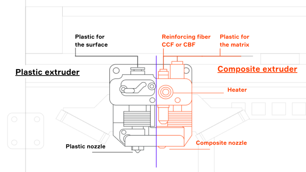
Note: Using the plastic extruder is not mandatory; you could print a part using only the composite extruder if you wanted to. However, doing so would result in parts with a lower tolerance and a poor surface finish– this is why the plastic extruder is needed.
Currently, Anisoprint offers two proprietary plastics for printing on the plastic extruder: Smooth PA and Clear PETG (which launched quite recently). For co-extrusion (the CFC nozzle), another two plastics are available: CFC PA and CFC PETG. The latter are co-extruded with continuous fiber filament: either carbon fiber or basalt fiber, for now.
During our visit, we used Carbon fiber and CFC PA with Smooth PA filament, which is about 90% polyamide 12 and 10% chopped carbon fiber. It is called Smooth PA because, at a microscopic level, the chopped fibers act like a fuzzy coating on the surface. The “fuzz” makes individual layers much less visible to the naked eye, as we can see in the images below:


The Smooth PA print’s surface is very smooth, while the purple Benchy has visible layers (though it’s still excellent for a desktop FFF print).
According to the Anisoprint team, this is the main reason why they add chopped fibers to their plastic matrix material; it is not for the enhanced strength, but for the sleek aesthetics. The real enhanced strength comes from the continuous strand of carbon fiber.
Why is 3D printing continuous fiber a challenge?
The main challenge of continuous fiber 3D printing is to make the fiber stick to the rest of the part’s structure. Standard continuous fiber technologies rely on simultaneously depositing the fiber and applying “glue” (a plastic mixture) to it with great pressure, so the glue can properly penetrate the fiber and entirely coat it. This process is sometimes called “impregnation”.
Since this is extremely difficult to perform within a single machine, Anisoprint pre-impregnates its proprietary fibers with a special polymer resin. Put simply: Anisoprint’s spools of continuous fiber are already “pregged”.
And during the 3D printing process, there is an in-situ coating of the fiber. Since the fiber is already impregnated, the CFC plastic acts as a binder for the pre-impregnated fibers to stick together. This in-situ coating is an exclusivity of Anisoprint machines, made possible by their unique extruder.
As the fiber is already pre-impregnated, the plastic coating’s volume can be varied (see fiber-volume ratio) without the risk of creating pores or other defects within the fiber strand. It is paramount for creating 3D printed lattice structures and enables a dramatic increase in part resistance. Thus, the printhead is capable of changing the plastic coating’s flow– i.e., its extrusion width– in real-time to increase the fiber’s adhesion (add width) or minimize its thickness (lessen width).

Composer A4: First impressions and overview
The Anisoprint team has integrated its CFC technology into several turnkey solutions. For “desktop Anisoprinting”, there are the Composer A3 and the Composer A4, which we are focusing on today. That said, both printers boast the same technology and features; they only differ in their build size.

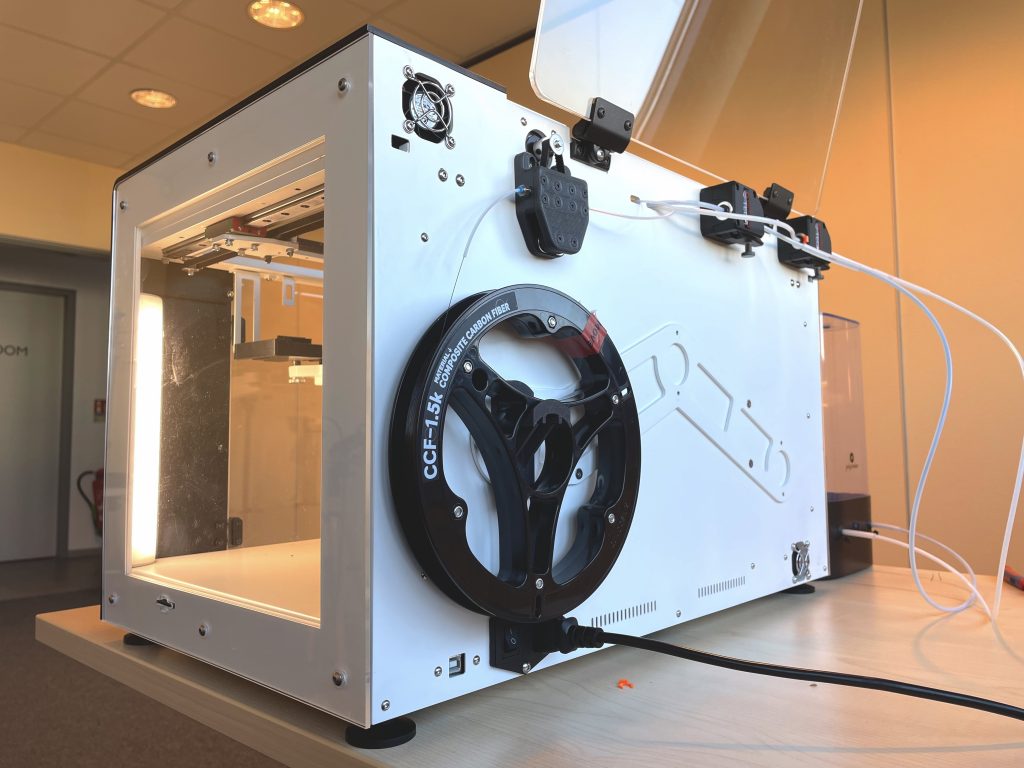
Anisoprint Composer A4 overview
The Composer A4 is a 3D printer produced by Anisoprint, a manufacturer based in Luxembourg.
It uses the Composite Fiber Co-extrusion technology to produce continuous fiber reinforced polymers and thermoplastics parts using filament feedstock.
It offers a build volume of 297 × 210 × 140 mm.
Their lineup also includes the larger-sized PROM IS 500 for “industrial Anisoprinting”. All three solutions work with Anisoprint’s proprietary software, Aura. It allows users to prepare parts with optimal carbon fiber reinforcement depending on their use case.
Hardware
Build volume
The Composer A4’s glass build plate measures the same as standard A4 paper, 297 x 210mm (the same goes for the Composer A3 and A3 paper size). In terms of build height, parts can go up to 140mm. One might ask, why not offer more height?
CFC technology’s strength lies in reinforcing parts in a directed manner, and it lays carbon fiber down horizontally. So it would make little sense to print tall, thin parts (see Fig.1, A) vertically if they must withstand front-facing loads, for example. In Aura, you’d just snap the model down flat to reinforce it correctly (see Fig.1, B). Your part would be much more resistant to said impacts, and you wouldn’t need a tall build volume.


Extrusion system
There are three Bowden inputs (for two nozzle outputs) on the print head: one for the plastic matrix material (Smooth PA), and the other two for the continuous fiber and its own matrix material.
There are two main reasons behind Anisoprint’s choice of a Bowden system.
- Belts for fiber feeding
The continuous fiber feeder, contrary to almost all existing FFF feeders, does not use gears to push the fiber forward. Pure continuous fiber is too brittle to be handled by gear teeth.
Instead, Anisoprint uses two belts: one is passive while the other rotates and pushes the fiber forward. Placing such a system into a direct drive on the print head would take up too much space and be far too heavy; it is more practical to have them on the printer’s backside.
- Fiber cutting mechanism
Another reason to save weight and space via a Bowden system is that the continuous fiber printhead needs room for its cutting mechanism. In regular polymer FFF, when a print is complete, you can “cut” the plastic by simply stopping its flow. But you can’t just stop a strand of fiber– it must be literally cut. Anisoprint’s answer to this is a sort of rotating hole made of high-strength, quenched steel.
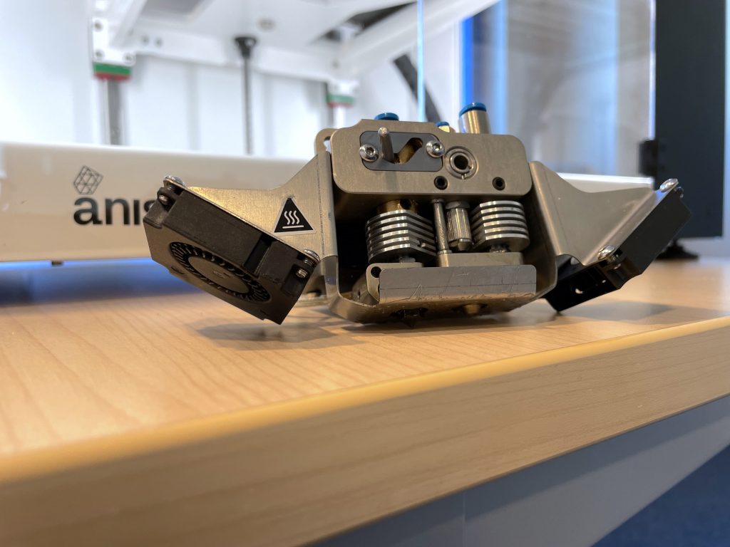
Printhead
The printhead features two nozzles. Again, one for the plastic, and one for the continuous fiber and its own plastic matrix. There’s a clever switch mechanism to shift between both nozzles (to avoid the idle nozzle from interfering with the print in progress).
Aura software writes the Gcode so that when the first nozzle has drawn one layer’s share of plastic, the printhead travels all the way to the front right of the printer to hit a switch. Hitting the switch makes the first nozzle rise and brings the second nozzle down to complete the layer in progress. The printhead must travel to the switch each time a material change is necessary.
These “trips” also enable the nozzles to move along the printer’s nozzle wiper, ensuring that no extra plastic oozes over the print in progress.


The printhead is equipped with heatsinks and specifically-oriented fans to prevent material clogging. As an additional precautionary measure, Anisoprint also designed a special air gap in its extruders; in case the material does clog, it leaks outside the nozzle and not inside, for easier cleanup and maintenance.
Materials
The Composer A4 boasts three material inputs that are extruded via two separate nozzles. Three spools are thus necessary to start “Anisoprinting”.
One spool of plastic
At the time of writing, Anisoprint offers two proprietary plastic filaments:
- Smooth PA (developed in collaboration with Polymaker), for a smooth appearance and reduced warpage.
- Clear PETG, for easy and quick preliminary prototypes and/or parts that require translucency.
These proprietary materials were designed to work with preset profiles in Aura (Neat and Ext versions) for guaranteed quality. It is only possible to use other plastics if you have an open material version of Aura.
You may also like:
One spool of continuous fiber
At the time of writing, two kinds of fibers are officially made and sold by Anisoprint:
- Carbon fiber
- Basalt fiber
Carbon fiber is stronger, stiffer, and lighter than basalt but conductive and not RF transparent. Basalt fiber is non-conductive, radio transparent, and is better for heat insulation.
If you need to experiment and try your own fibers, you can with the Open software version. But Anisoprint can therefore not guarantee results and you must take great caution not to damage your hardware. The Open version and its ability to use different fibers (e.g. continuous aramid fiber) is a good solution for advanced researchers and material developers.

One spool of matrix plastic
Fibers must be 3D printed along with a plastic matrix for them to stay in place and in the right shape. The plastic matrix is often the same material as the first plastic. For example, if you are 3D printing Smooth PA (nylon 12 with chopped carbon fiber), you will need to use Anisoprint’s CFC PA12 (from the nylon family as well) matrix. The latter contains additives to reduce the material’s viscosity and better coat the fiber.
Aura software
Aura slicing software is easy to apprehend while being powerful and adaptative. It is available in three versions to cater to different user knowledge levels and material needs:
- NEAT PACK: In this version, you can only work with Anisoprint’s proprietary materials. It was specifically optimized for these materials and enables inexperienced users to easily obtain great, reliable results. The idea is to make sure that beginners have less room to fail; with time and experience, though, they can come to understand the parameters and how they can adjust them. At that point, users can switch to the next version, Ext. Pack.
- EXT. PACK: This “Extended” version still has a lock on numerous settings, but lets you use verified third-party materials via profiles with preset parameters. It includes a 6-hour training course and an extended, three-year warranty plan.
- OPEN PACK: The Open pack offers the ultimate level of freedom. You can use any plastic and any fiber, as all the settings are unlocked. For this version, Anisoprint provides 2 days of training. It also includes the aforementioned three-year warranty, and throws in the possibility to change the entire printhead for free.
Our experience with the Composer A4
Material loading
Material loading is as easy as with other standard FFF 3D printers, you just need to push the filament through the three different Bowden inputs.
It is highly recommended to use a filament dry box unless you’re doing a very short print and have previously dried the filament. PA6 has about 2.3% moisture absorption, so you definitely can’t print it without a dryer, but their proprietary PA12 has a lower moisture absorption rate of 0.2%.

There are no sensors to detect filament outages. Thus, before launching a print, you must check how much material you’ll need (via Aura) and ensure there’s enough of it on your spools (or that you’re available when it needs reloading). Today, filament detectors are present on most professional FFF 3D printers; we think the Composer series deserves this feature, too.
Calibration
It is necessary to calibrate the printer once in a while but also when the nozzle is changed, if the build plate is removed after a print, or when the printer is moved around. We found that the calibration process on the A4 was tedious and comparable to previous generations of desktop printers, both for the print bed and the nozzle offset. More details below.
Leveling the print bed
To level the print bed, you first need to heat it up to the working temperature via the Composer A4’s touchscreen interface. This is due to thermal expansion; the cold build plate’s shape and size can vary (very) slightly compared to its dimensions when hot. And as many 3D printing professionals know, even the slightest offset can throw off a print.

The process, semi-automated, goes as for any regular FFF 3D printer: the build plate must be verified at all corners, in the middle, and at several points in between.
It’s up to the user to manually tighten or loosen the print bed’s screws according to the data displayed on the touchscreen. Once all of the screws have been calibrated, the process must be repeated, because adjusting one screw can decompensate others.
Determining nozzle offset
After ensuring the print bed is correctly leveled, it’s the nozzles’ turn to be calibrated. Note that materials must have been loaded first. You roll on a layer of Magigoo, and then select a special Gcode file via the touchscreen. The file instructs the printer to draw a sort of grill on the print bed, and a single line that is supposed to be in the exact middle of the grill’s cells:

The printhead draws a first grill for the X-axis and a second one for the Y-axis. If the single line is not perfectly centered, you must adjust the nozzle offset accordingly via the touchscreen.
In the video below, you can see the Composer A4 printing the nozzle offset calibration Gcode and Fedor removing it from the build plate:
3D printing parameters
- Microlayering
As the machine manipulates different materials of varying thicknesses, it is important for the software to be capable of handling this complexity in a simple way. To answer this need, Anisoprint came up with a concept called “microlayering”. It allows Aura to locally optimize the thickness of each layer to (a) save time while printing the matrix, and (b) offer a maximized surface quality on the outer faces of the parts.
For example, in the illustration below, we can see that the outer, visible surface of the part is printed in a thickness of 0.12mm. The inner, non-visible infill however is printed at a thickness of 0.18mm, and the reinforcing fiber is even thicker, at 0.36mm. Of course, each layer height variation must be of the same multiple (in this case, a multiple of 6).

For more information, take a look at Anisoprint’s macrolayer explanations.
- Reinforced infill
There are five different types of infills available: one solid, and four kinds of lattices (rhombic, isogrid, anisogrid, tetragrid) to provide different mechanical properties.

Straight carbon fiber is very strong in one direction, but can become up to 20 times weaker in the other (remember Fig.2). By using a lattice, you distribute the fiber’s properties along the lattice’s ribs, so that it is just as strong or resistant from whichever direction you apply force. Lattices are what give Anisoprint parts their strength as well as their compression, flexion, and bending resistance.
You can even use different kinds of lattices within the same part via the “mask” option in Aura Premium (a paid DfAM plugin).
- Masks
When planning the fiber’s lattices and orientation is not enough to boost a part’s resistance, Anisoprint software offers even more advanced options. Masks are one of them.
Let’s take the fixture below to illustrate why they are sometimes necessary. The fixture must withstand force and stress coming through the three holes. The top two holes are fixed, while the bigger, lower one bears the load:

Below, neither CFC approach truly reinforces the three areas where stress is applied. The resistance of each hole is quite individual:

To better link them together, you might need to choose a solid infill, knowing that a solid infill uses up way more material (hence drastically increasing costs) and takes much longer to print.
Anisoprint yet again came up with a simple and clever solution. Like with dual-color 3D prints, the trick is to actually export two different 3D models from the source file, and to attribute different fiber infills to each of them.

For our fixture example, it means that it’s possible to strategically reinforce the main force/strain axis without wasting material on areas that won’t withstand much stress. The final result is a very strong part that is perfectly optimized for its function:

- Fiber-volume ratio (FVR or FVF)
The fiber-volume ratio (or fiber-volume fraction) corresponds to the ratio of fiber used in a fiber-reinforced composite part. With Anisoprint’s technology, the maximum fiber-volume fraction is around 65% (70% in joints). The lower the ratio of fiber, the less the parts will require consolidation and the more they can be optimized. Parts with a fiber content of 20% are still much stronger than parts made of 100% plastic, and allow gains in price, print time, and part weight.
- Anisoprint academy
Every Anisoprint client gains access to some level of training when buying one of their machines. There is a different level for each version/pack of Aura software (NEAT, EXT, and OPEN).
The more options and settings you have access to, the longer and more complete the training is. The training that comes with the EXT version lasts 1 day and covers the basics of composite 3D printing and how to operate the machine.
With the OPEN version, the training is extremely complete and covers very advanced notions about composites and how to design composite parts. It even includes some very advanced know-how on material research.

As we were already familiar with the subject and the printers, we opted for a custom, condensed (3.5 hours) version of the OPEN-level training. It was nonetheless intense and rich with learnings.
Anisoprint’s partner AM Academy performs these training sessions. Our session was led by a very pedagogic trainer (cheers, Sven Bagger!); he was very knowledgeable and capable of explaining complex information in a simple manner.
We believe that the training Anisoprint provides via AM Academy can really help users get the most out of their Composer printers. One could even go so far as to say that it’s a must for anyone in the additive manufacturing industry.
3D printing results
Our review focuses on the Composer series’ workflow and user experience. Hence, we will mainly comment on the parts’ visual quality and appearance.
Lever (demo part)
This lever is one of the demo parts available directly on Aura software. It came out very nicely in a few hours and has perfect-looking first and last layers, aside from a tiny bit of stringing that we easily sanded away.
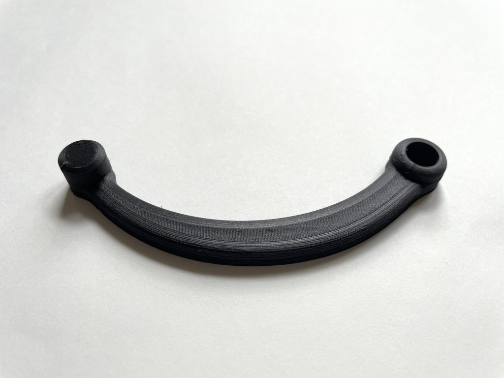
Cap opener
The cap opener came out beautifully as well, with a very smooth outer surface. We had the opportunity to test it as soon as we finished the review 🙂

Compared to previous versions we did in PLA and then in ABS of the same file, it came out much sturdier. The PLA broke after only a few uses, the ABS survived a few more cheerful evenings and the composite we did is still intact!
Festool guide stop
This guide stop is designed to avoid kickback when using a Festool plunge-cut saw and guide rail. Kickback can cause serious injuries if not quickly controlled, and it can damage the wood you’re working on.
Ludivine’s partner has this machine, so she thought of him when looking for practical test prints.
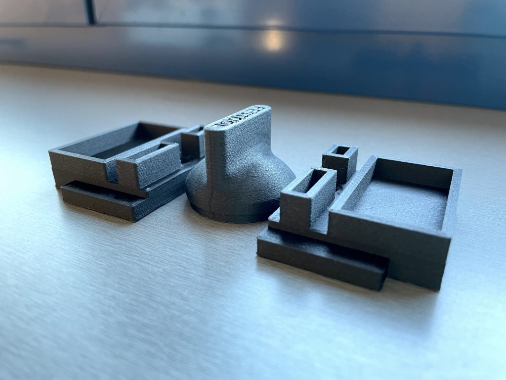
In terms of appearance, each part looks very smooth and feels strong in hand. We just later added an M6 screw and assembled the parts, which fit perfectly into each other.
Conclusion: Our verdict
While the technology behind the Composer A4 (and A3) is incredible, we felt that the machine’s design and workflow were several years late. The steps you must take to level the bed, calibrate the nozzle offset, and perform maintenance need some rethinking, in our opinion.
However, the final results that can be obtained are truly exceptional and one-of-a-kind. At the time of writing, there is simply not a single competitor capable of achieving such a performance in this price range. Even Markforged, one of the reference companies in the composite field, has lesser capabilities, as they are not capable of offering such a high fiber-volume ratio.
Anisoprint let us grasp a part of the future they envision with their next products, including their soon-to-launch industrial hardware (PROM IS 500); we can confidently say that composite 3D printing is only at its very beginning and that great, exciting perspectives lie ahead!