English
  Français
Reviewing the GOM Scan 1 at GOM’s Benelux HQ


Introduction
GOM is a leading industrial metrology solution provider based in Germany since 1990. The company was acquired by ZEISS in 2019 and continues to deliver high-quality 3D scanning solutions for professional and industrial applications. The automotive industry is one of their most demanding clients. They offer a complete range of solutions to cover their needs, from small part 3D scanning to full-body, in-line inspection.
At the start of the Covid pandemic in 2020, we met with the GOM team online to carry out a virtual review of GOM’s ATOS Q 3D scanner. It was a smooth experience despite its virtual nature, and we witnessed first-hand GOM quality on both hardware and software aspects. We were also amazed to discover how relatively small the ATOS Q was compared to the ATOS 5, GOM’s top-of-the-line 3D scanner.
This time, we were excited to visit the GOM team in person at their Benelux HQ and try out their latest solution, the GOM Scan 1. The offer? GOM quality and performance at an affordable price.

| Country | Germany |
| Category | Desktop |
| Technology | Structured light |
| Max resolution | 0.037 mm |
| Weight | 2.5 kg |
| Price | upon request |
GOM GOM Scan 1 overview
The GOM Scan 1 is a 3D scanner produced by GOM, a manufacturer based in Germany.
The GOM Scan 1 GOM uses the structured light technology.
Of course, the GOM Scan 1 isn’t as performant as the more industrial and expensive ATOS lineup, topped by the ATOS 5. It is also less flexible in use cases due to its fixed camera optics and field of view, so the type of parts to be 3D scanned must be known beforehand.
But, as we will see in this review, it is still on par with high-end portable metrology 3D scanners and even does very well with shiny, reflective surfaces. It captures 6,000,000 points per scan, and benefits from the same, powerful GOM Inspect software as its more premium counterparts. The GOM Scan 1 is a small and light machine, packed with very serious capabilities.
Before we dig in, here’s a quick summary of the GOM Scan 1’s of pros and cons:
 Pros
Pros
- Robust hardware
- Powerful software
- Intuitive workflow
Cons
- Fixed field of view
GOM Scan 1 overview
Only a few years ago, GOM’s entry-level solution was priced at €60,000. GOM has since then worked hard on packing their quality and performance into more affordable deals, bringing that price point down to a disruptive €20,000 with the GOM Scan 1.
The GOM Scan 1 works with GOM’s Blue Light Technology, more commonly known as structured light. It projects a fringe of blue LED light– i.e., a striped pattern– onto an object’s surface and captures its deformation with two stereo cameras to calculate the object’s shape and size.

The achievable resolution varies from an impressive 0.037 mm to 0.129 mm (point-to-point distance) depending on the chosen configuration. Indeed, GOM’s Scan 1 is available with varying fields of view, a.k.a. scanning volumes, to scan objects of different sizes:
| GOM Scan 1 (100) | GOM Scan 1 (200) | GOM Scan 1 (400) | |
| Resolution | 0.037 mm | 0.060 mm | 0.129 mm |
| Field of view | 100 x 65 mm² | 200 x 125 mm² | 400 x 250 mm² |
| Working distance | 400 mm | 450 mm | 500 mm |
As previously mentioned, it’s also one of the factors behind the scanner’s lower price: it isn’t possible to swap between fields of view by simply changing its lenses like it is on the ATOS Q, for example. Note that we used the GOM Scan 1 (400) during this review.

If you’re doing metrology in a quality control department, you probably already know the typical dimensions of the parts that land on your desk. You can therefore have a good idea of the scanning volume you need and might determine that the GOM Scan 1 (200) will do the job for most of your parts.
If you do need the three scanning volumes, to scan different-sized parts for several clients, you’ll have to buy the three GOM Scan 1 configurations or a more flexible solution such as the GOM ATOS Q.
GOM has planned for the triple-scanner situation by creating a practical transportation case that fits all three scanners and their respective calibration plates, plus other accessories like the tripod, the automatic turntable, and cables. There’s even a small cutout in the protective foam designed for strips of adhesive markers (positioning targets).
A smaller transportation case, included by default, is available to fit a single GOM Scan 1, as most professionals already are equipped with a tripod. Both cases are very robust and well-organized, and can fit into most standard car trunks for easy transportation.
This 3D scanner can be used in different setups, as well:
- Mounted on a tripod with or without an automatic turntable
- Mounted on an automatic, desktop scanning station
- Mounted on a movable arm/stand with or without an automatic turntable
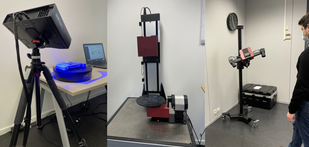
Only the fully automatic, robotic arm configuration is unavailable for the GOM Scan 1 for connectivity reasons. Such configurations are preferred for high-end metrology applications requiring even more industrial-grade precision (and scanners) anyway. The GOM ATOS 5 and GOM ATOS Q, for example, can be mounted on a robotic arm.
You may also like:
Practical guide to automated metrology 3D scanning with GOM solutions

Overview of GOM Suite and GOM Inspect Pro software
The GOM Suite is a new, all-in-one platform that groups all of GOM’s online services (e.g., training courses, e-books, forum, automatic updates, …) and software solutions. GOM’s software offering includes GOM Inspect Pro, which we used during the review, as well as application-specific software such as GOM Blade Inspect Pro, GOM Volume Inspect Pro, or GOM Correlate Pro. GOM Suite is also a gateway to ZEISS software like ZEISS Reverse Engineering, for example.

GOM Inspect Pro is the software used to operate the 3D scanner from a PC, but it also does much more: it is one of the 3D scanning industry’s most well-rounded part inspection software solutions.
The GOM team told us that, last year, their software development department had focused most of their efforts on enhancing the software’s user experience and interface. Their goal is to make the workflow as easy as possible for any user, from beginners to experts.
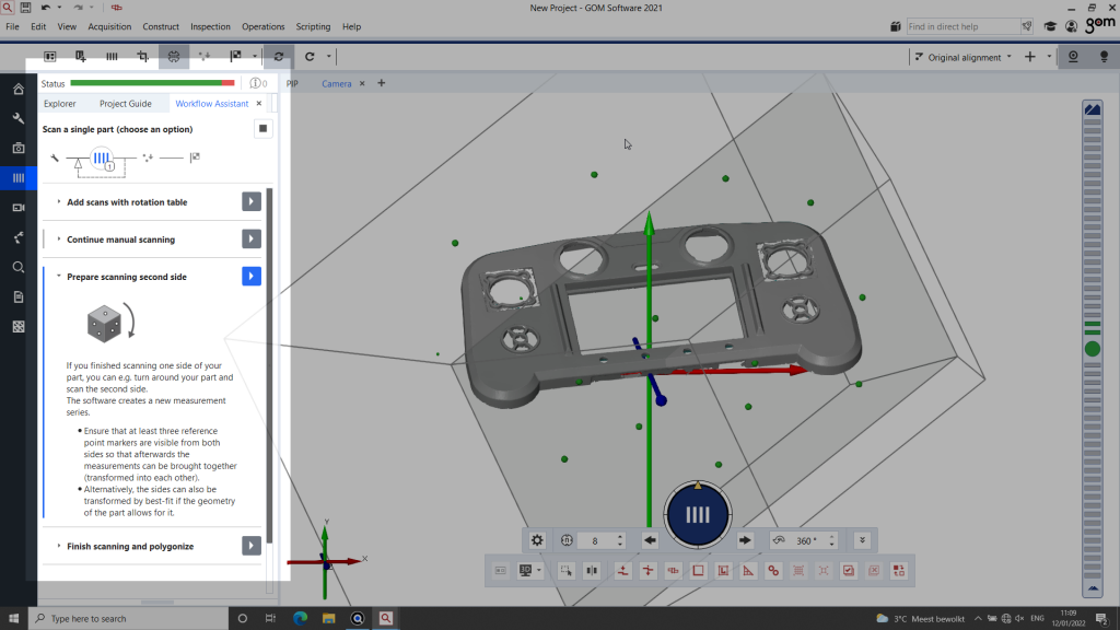
This is definitely something we noticed while using GOM Inspect Pro and its new Workflow Assistant, which offers informative, step-by-step guidance during the 3D scanning process.
GOM also developed new functionalities, namely:
- Multi-part scanning, where the software auto-detects multiple objects and generates separate meshes;
- Dewarping, which offers the simulation of an assembly situation;
- and the ability to “rebuild” objects in 3D from scans of an object’s different components.
GOM Inspect Pro’s automatic inspection reports also now boast 3D previews when visualized within the software.
Our experience with the GOM Scan 1
Hardware and setup
The GOM Scan 1 sensor is compact and quite lightweight. It feels very “German”, with a robust casing, precise finishes, and an efficient, sober design.
We tried it in its tripod configuration with the included tripod, which is stable and robust. It was already set up when we arrived, but we did reposition the scanner several times to capture different objects from different angles. The process involves little more than loosening and tightening a bolt with one hand, while firmly holding the sensor with the other.

The turntable is robust as well and, once it is plugged in, works automatically with GOM Inspect software. Markers are positioned on the table’s surface to help the 3D scanner align scans, and they must be replaced from time to time as they wear out.
Note: The GOM team recommends the tripod/turntable combo when on the road. For everyday, in-office scanning, they prefer to use the stand on wheels as it is easy to roll around the room or table.
Calibration
To ensure it provides the best accuracy, it is necessary to calibrate the 3D scanner. There is one calibration plate for each scanner (GOM Scan 1 100, 200, and 400) and its field of view. Of course, the larger the field of view, the bigger the calibration plate.

You must first place the adequate plate on an included collapsible support. Then, the software guides you through several easy steps, i.e., positioning the plate at different distances from the scanner and tilting it on the pitch and yaw axis (tedious roll-axis tilting isn’t necessary).
The entire calibration process takes under 5 minutes, and even less the more you get the hang of it.
Getting started
When the sensor is turned on (with or without previous calibration), the software automatically detects it and senses the distance between the part and the sensor. The scanner projects a frame of light to show you what the scan area covers, as well as a dotted pattern, which much be focused on the part to offer the best 3D scanning results.

The appropriate distance is displayed on the right-hand side of the software’s interface, with color-coded indications (the usual green, orange, and red) of whether you need the 3D scanner moved closer or farther away from the part. Its sensitivity is easy to apprehend, and it is intuitive to reposition the scanner or part at the perfect distance.
Once you’re ready, you can choose your 3D scanning mode: Advanced or Guided. GOM Inspect Professional’s Guided mode walks users through the workflow, suggesting preset parameters and actions. According to the GOM team, this user-friendly mode works great for more than 80% of use cases and helps save time, even for very specific applications.
Using the guided mode does not, nonetheless, impede users from accessing GOM’s expert software features. This mode is like the key to driving a powerful F1 car without the hassle of learning how to do so, while offering you the freedom to change the car’s injection parameters in a breeze if needed.
3D scanning
Once you’re in the Guided mode and before you start 3D scanning, you must first choose between Single-part or Multi-part scanning.
After that, the software displays a choice of several scanning templates, each fit for different types of surfaces (sheet metal, sand, …). We chose the “Robust scanning” template to obtain the best possible results, though it takes longer than modes that are streamlined for specific materials or surfaces.

The 3D scanner starts by illuminating the part with different light intensities and fringe patterns, acting like a configurator for the upcoming 3D scans. It allows the system to identify the best shutter time, light intensity, and distance between it and the object. At that point, the software also offers automatic detection and deletion of the background.
You then further narrow down the possibilities and parameters by selecting the configuration you’re using: Rotation table, Markers, etc. The GOM Scan 1 can work with photogrammetry references, markers, or no reference at all. In the latter case, the part itself will serve as a reference.
Note (1): When you operate an industrial metrology machine worth tens of thousands of dollars to get precise results, you generally use markers. You only need to take a few seconds to stick a few markers, and they really accelerate and facilitate the 3D scanning process.
Note (2): GOM only uses and recommends their proprietary, certified markers for certified accuracy. It is possible to use third-party markers, but then GOM cannot guarantee that their scanners will achieve the announced precision specs.
It is easiest to work with the rotating table, a relatively cheap accessory when compared to the total cost of ownership of the 3D scanner. Once dressed up with markers on its surface, it can significantly speed up any 3D scanning process.

We used the turntable for most of the scans we did during this GOM Scan 1 review. The software lets you choose how many rotations you would like, the total rotating value, and other settings.
Although all of the above may seem like a lot of steps, each one is quick and easy to do. The GOM Scan 1 is actually quite “plug-n-play”, which is rare to come by in the industrial 3D scanning world.
After each scanning series– several 3D scans where the part remains untouched on the rotating table– the software prompts the option to:
- perform new scans (which will be added to the series),
- or to fliip the part over to scan a “further” side of the object, therefore triggering a new series.
As French speakers, we found some terminology to be a bit confusing (“further” vs “other” or “additional” side; “transform” vs “match” or “align” 3D scans) and suggested some changes to the GOM team that might be implemented. Also, the legacy 3D scanning icon (4 vertical bars, likely representing a fringe pattern) is not very explicit. But it is always difficult to redesign such an imported UI element without losing your (huge) installed professional legacy base.
Software features
Throughout the scanning session and various parts we captured, we discovered several interesting functionalities present in GOM Inspect Professional.
Multi-part scanning
This is a brand new feature and it is impressive, to say the least. As its name suggests, this feature enables you to 3D scan multiple parts in one go. Now, this has always been possible, but extremely time-consuming with manual cutouts or writing custom scripts.

What’s major here is that the software automatically detects separate parts and produces individual files (meshes) for each of them. It projects a set of virtual boundaries, dividing the surface (of the turntable, for example) with a grid or pie cut. You can even compare parts to each other once you’re done scanning– practical for quality control, for example.

Part assembly and analysis
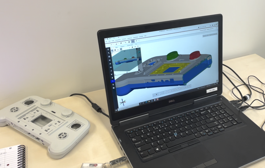
If you scan separate parts of the same object, let’s say the top and bottom half of a casing (like on the drone controller below), the software is capable of assembling the 3D parts and rebuilding the object. You do, of course, need to manually indicate which part goes where.

Following the same casing example, when you have your two parts in 3D, the software can show a color map to highlight distances between the top and bottom halves. The goal is to help users understand how well different assemblies can fit together.
Dewarping
This powerful tool allows users to simulate how parts will behave once assembled, based on the mesh of each individual component.
Assembled parts do not always behave the same as when they are “single” and on the shelf, free of pressure or constraints from other parts or loads. In our example, the drone controller casing is made of two, flanged parts. With this feature, it is possible to simulate how they will behave once the assembly screws are in, and how much warp will remain.
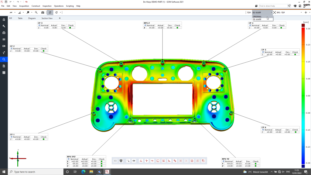
There are many tunable parameters– such as the part’s material or the force applied by the screws– to help precisely measure the gap that would remain, once assembled, between the top and bottom cover.
Workflow assistant
The Workflow Assistant is GOM’s way of making their software intuitive and easy to use. It displays definitions of complex steps for users to understand what they are doing and why, as well as reminders and tips.
For example, when you move your mouse while a scan is still in progress, a warning pops up. Or, if you scanned something and didn’t add it to your report, a message appears to warn you, too. It is kind of like when you send an email with the words “file attached”; if there are no attachments to your email, Gmail warns “There’s no attachment. Are you sure you want to send?”. It is like a powerful, functional version of the infamous Microsoft Clippy helper.
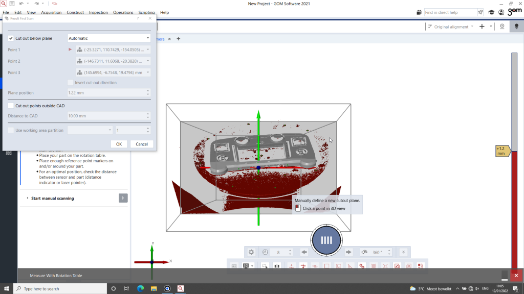
Automatic plane clipping
This feature isn’t new, but it is worth mentioning. GOM software pre-detects and segregates the part from its context (table surface, surrounding walls, …). In two clicks, it is possible to 3D scan only the part itself, so you don’t have to spend time and effort cleaning unwanted information. Of course, manual operations are still available to define a plane, area, or volume cut.
3D scanning results
The drone controller, designed in-house by GOM (wink Wim Cuypers!), is the typical sample part that they use to demo the full GOM Scan 1 lineup. It’s made of plastic (injection-molded) and features five parts of different part sizes that each correspond to a field of view:
- (100) Very small parts: two knobs, about 2cm in diameter and 2cm tall
- (200) Small part: a screen holder, about 10cm x 7cm
- (400) Medium parts: the two halves of the casing, about 30cm x 15cm
The GOM team used the latter part to show us how to use the GOM Scan 1 and GOM Inspect Professional.
To push the scanner out of its ideal conditions, we used the scanner and software on our own to capture an exhaust pipe part of about 25 cm long. We settled for a process without the rotating table to spice things up. We also sprayed our special AESUB 3D scanning spray (which leaves a powdery, matte white finish where sprayed) on only half of the part to compare results with and without spray.

After a short, 15-minute session we obtained a very detailed model, with only a few holes remaining in the shiny, non-sprayed area of the part. We could have acquired the lacking data with some extra scanning steps (or spray), but we left it as-is to test GOM Inspect’s mesh cleaning features.
During the file preparation process, we did three major operations:
- Automatic hole filling: You simply define the maximum size of the holes you want to fill, how they should be filled, and the software takes care of the rest in mere seconds.

- Smoothing of artifacts: Sometimes, reflective surfaces can create unwanted “bumps” on the surface of the mesh. For these situations, the software boasts a smoothing tool. You can define the tool’s “influence zone” and correct the mesh in a single click. The approach strongly reminds me of the patching tool in Adobe Photoshop.
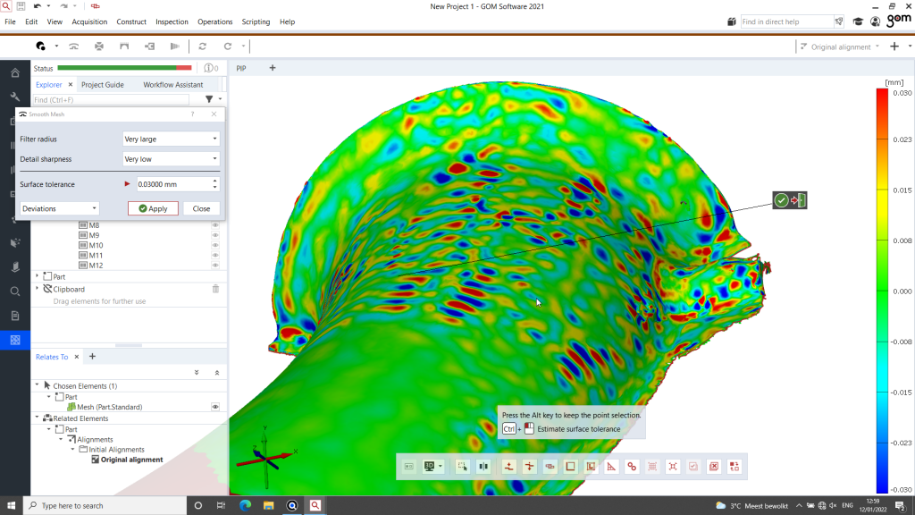
- Smoothing of the mesh: A very useful interface activates and directly colors the mesh to show you where it will be modified, while staying inside a specified threshold. It’s a handy feature that lets you see the result of an operation (not only for the smoothing tool) before applying it to the mesh, like a preview.

We were impressed by the level of detail that the GOM Scan 1 captured, and on a simultaneously matte (sprayed area) and highly reflective (sprayless area) part.

Our verdict
GOM announced high-quality results and an easy workflow at an affordable price, and we were not disappointed.
Regarding the hardware, the scanner (priced at about €20K) is robust and qualitative. The GOM Scan 1 managed to capture a very fine level of detail, as we saw with the metal exhaust part. It is also, just like the software, extremely fast; you can obtain scans in minutes, especially with the automatic turntable.
In terms of software, GOM Inspect Professional and its new (and old) features– like multi-part scanning or dewarping– are super impressive. Although the interface could be even more optimized (there are many buttons and features), it’s the best scanning and inspection software we’ve had the chance to try. The workflow assistant brings great value and ease of use. This professional inspection software solution is available at around €12K.
Combined, the GOM Scan 1 and GOM Inspect Professional can amount to a relatively big investment. But, 3D scanners with this level of precision and accuracy usually cost much, much more. By compromising on non-crucial elements, like swappable lenses or robotic arm compatibility, GOM is able to introduce its industrial-grade metrology to smaller companies and professionals.